LV FEM – A new Tool
Finite element calculations have matured into a standard procedure with which diverse load situations of the most varied geometries can be modelled with a high degree of accuracy.
In particular, this type of calculation requires, on one hand, technical knowledge in dealing with the respective calculation software and, on the other hand, experience in evaluating and judging the results..
With our FE Toolbox, we offer the solution to this challenge, so that even the inexperienced user can quickly and reliably obtain auditable results for his design.
New Standards
The new FE Toolbox from Lauterbach Verfahrenstechnik GmbH combines precision and user-friendliness in one application.
Our tool is tailor-made to reliably achieve a fast and accurate design of various components in pressure vessel design and plant design.
With COMSOL Multiphysics (formerly FEMLAB) we have a strong partner in the field of finite element methods. COMSOL Multiphysics offers the possibility to develop precisely tuned applications to make complex calculations accessible to a wide range of users. We have applied our expertise in the field of finite element calculation and our know-how from 30 years of engineering practice in apparatus construction and developed a new unique application that delivers valid results in the shortest possible time and does not require any knowledge in the field of FEM.
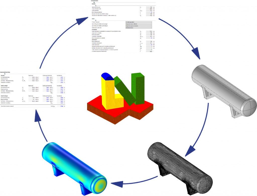
Everything from a single source
- CAD model creation
- Setting up the simulation environment
- Meshing to the finite element model
- Solution and presentation of results
- Evaluation of results according to DIN EN 13445, AD 2000 or ASME VIII
- Presentation of the results with powerful rendering
In the following, we would like to present our newly developed, customised FE Toolbox and its application possibilities to you.
User Friendly
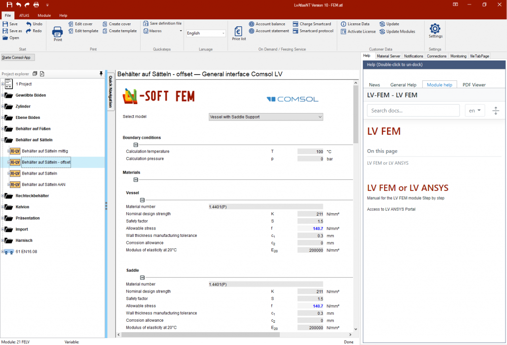
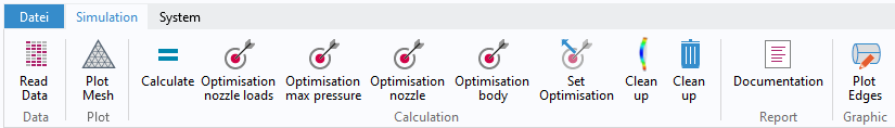
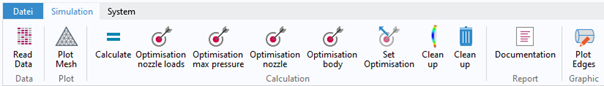
The handling of our new FE Toolbox is very simple.
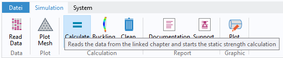
After entering your boundary conditions in the revised LV-Soft interface, such as material parameters (material server integrated in LV-Soft) and geometry data, you start the application via a button in the LV module.
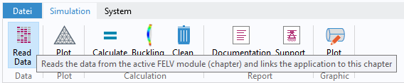
Here you can start the FE analysis with „Calculate“. After a successful calculation run, all relevant results are automatically entered in the LV-Soft interface and you can directly see whether your component is sufficiently dimensioned.
If you now want to change input data and have them recalculated, you only have to change your values accordingly in the LV-Soft interface and trigger the new calculation via „Calculate“ in the application. All data is read in again and the calculation is carried out.
FE analysis can be that simple.
Presentation of results
Being able to correctly interpret and categorise the results of an FE calculation requires a lot of experience from the user in this field.
Which quantities are relevant? How are different areas categorised and evaluated accordingly? What needs to be taken into account when equivalent stress values are too high?
Modern regulations such as AD 2000, DIN EN 13445 or ASME VIII specify how a component is to be classified and categorised. A distinction must be made between general and local areas. But when is an area to be classified as local or general? With our new tool, these questions are already clarified for you. We evaluate all results according to their type of origin and locality and compare all relevant variables with the permissible values. For you, one look at the results table is enough to know if the component is sufficiently dimensioned.
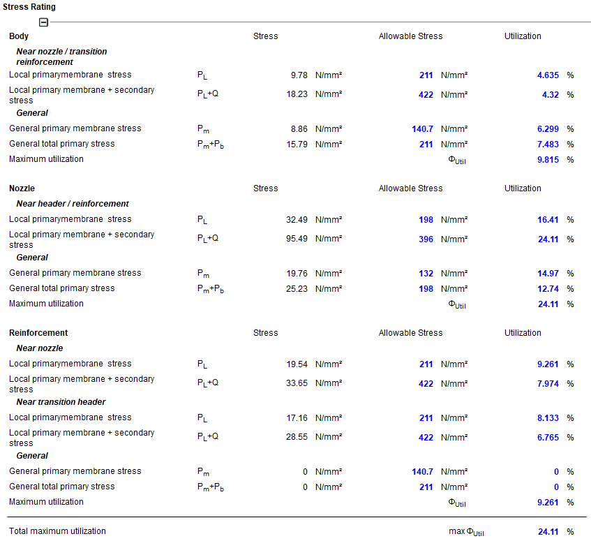
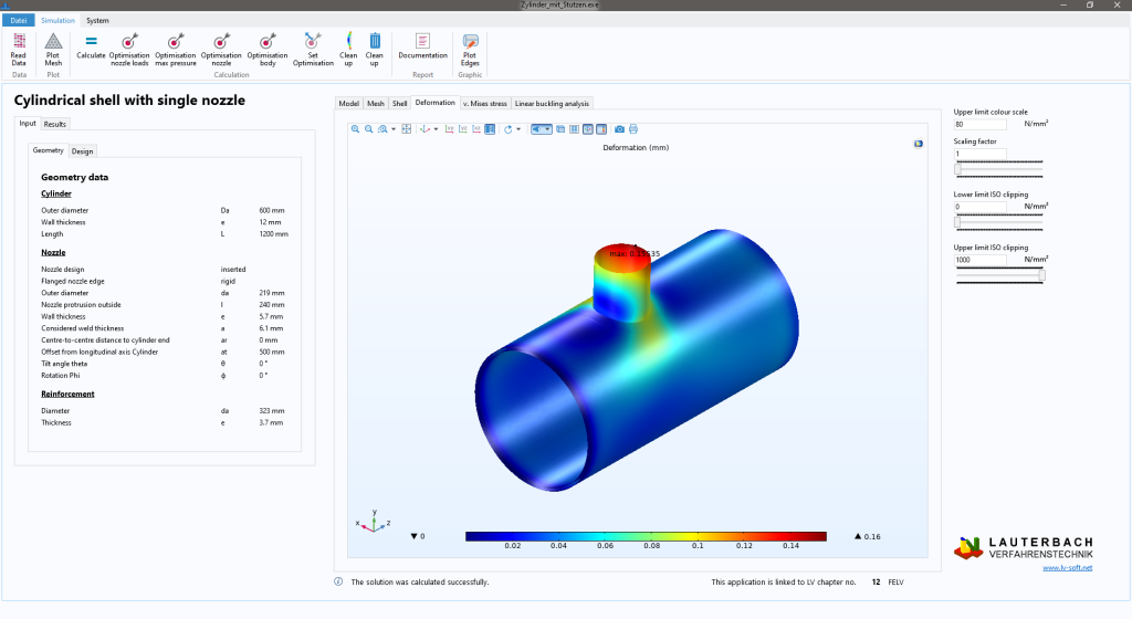
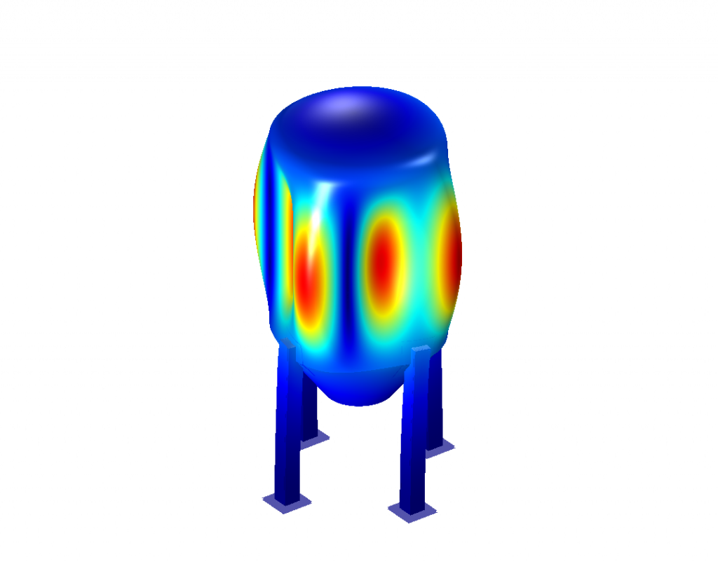
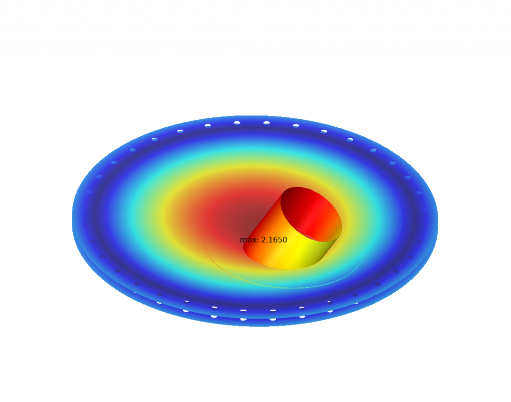
In addition to the tabulated maximum values, the modern graphical representation within the application gives you the possibility to gain insight into the load situation of your component at any time.
You can analyse and evaluate detailed areas. All relevant results for stress categorisation are displayed separately as an overall view or as separate individual components.
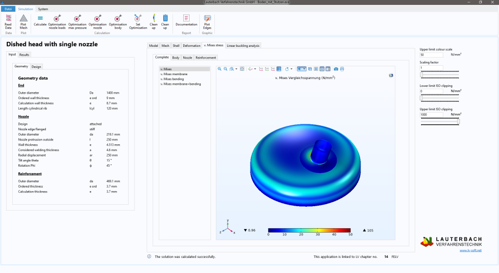
In addition, you can adjust the representations so that, for example, the deformation is strongly exaggerated in order to evaluate the plausibility of the load reaction. Or you can set limits with which you can determine ISO surfaces that only represent stresses in a certain range. This helps in the detailed analysis as well as in the evaluation of the results obtained.
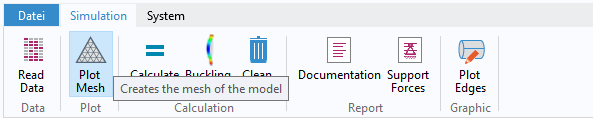
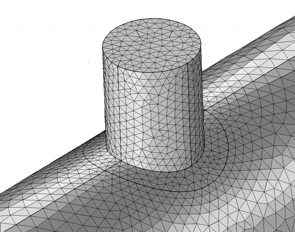
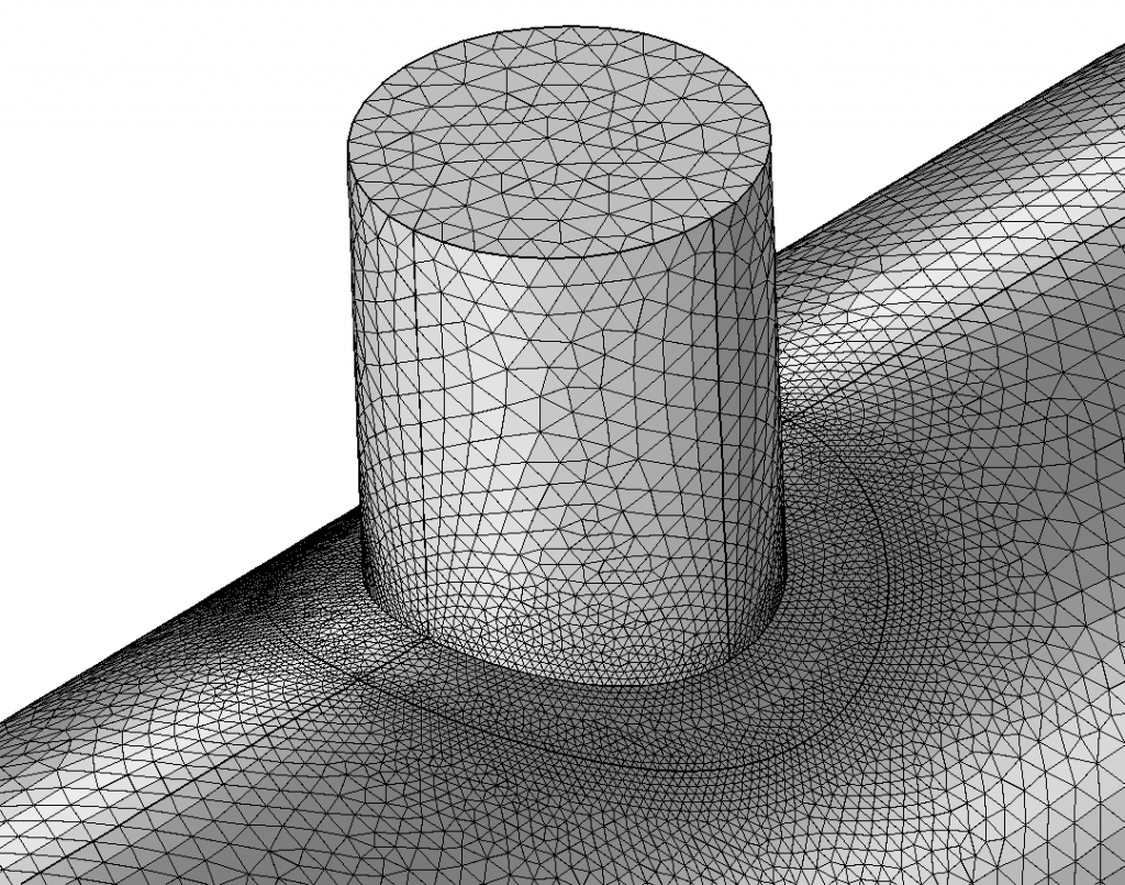
Mesh Control
No FE calculation without a mesh. Finite elements are created when a model is divided into closed, clearly defined elements. The continuous form of your model becomes a discrete form. The process of this division of the geometry into individual elements is the meshing.
Here, too, the less experienced user is faced with many questions. Which elements should I use? Which algorithm is the most suitable? How finely should I mesh? These and many other questions are typical.
Here, too, you do not have to worry about anything. All the meshing options have already been determined and are optimal for the respective application. Nevertheless, you have one tool in your hand – the element size. Since the calculation takes every mesh node into account, the calculation time increases rapidly with the fineness of the mesh. If you are still in an early phase of development, rough results are usually sufficient to see whether the load is close to a valid range. In this case, it is advisable to start with large elements and only select a finer, more precise element size for the final calculation. This saves a lot of time and therefore money.
In fact, the element size is the only size of the internal FE calculation that you have to specify. But this is exactly where another strength of our tool lies. You decide whether you want to carry out a very precise, possibly final, calculation or whether you want to calculate a first rough estimate. It is your time that you can save with it.
Proof of loads
Proof of local nozzle loads
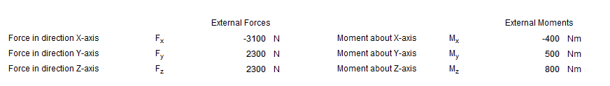
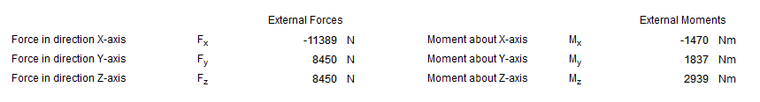
Components experience different loads due to their integration into an environment. In apparatus engineering, pressure loads as well as forces and moments are essential. In the past, axial forces and bending moments at the nozzle could be verified for the verification of local nozzle loads on cylindrical shells, curved or flat bottoms. Nowadays, torsional moments and shear forces also often have to be verified. This can only be done with an FE calculation.
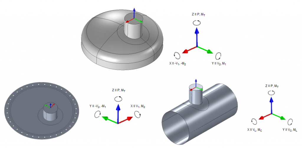
Our new tool is tailor-made to perform exactly these verifications – and for any nozzle configuration. But we can do much more.
Proof of load-bearing capacity
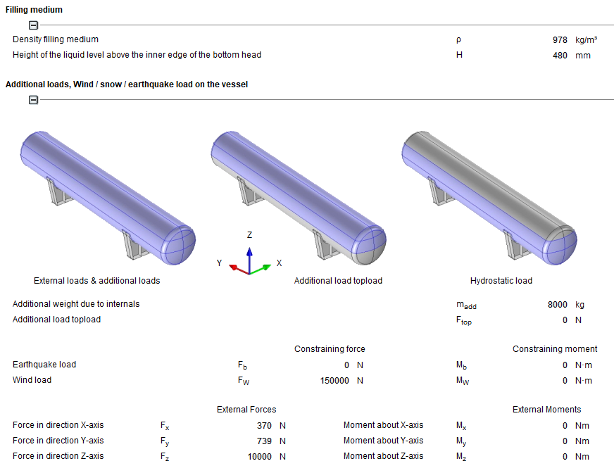
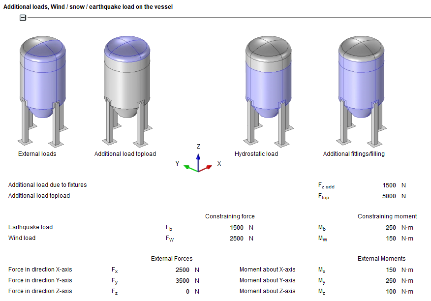
In addition to the load due to their integration into an environment, load-bearing structures often experience other, extraordinary loads. These can be, for example: Wind loads, snow loads and earthquake loads or also special loads due to an assembly device and much more.
With our tool, you have the option of applying additional external loads to a container on support feet or support saddles in addition to the load during operation due to, for example, hydrostatic filling and internal pressure.
Forces and moments in and around all three spatial directions are possible here, as well as wind loads, roof loads (e.g. snow load) or earthquake loads. This means you can map all relevant variables and use them to carry out your load-bearing capacity verification. In addition to the pure strength, the stability also plays an important role for the load-bearing capacity verification. Here it must be shown that the load-bearing elements do not buckle or buckle. Here, too, you have the possibility to check this with the help of the linear buckling analysis. What exactly this is and what it provides you with is described below.
Linear buckling analysis
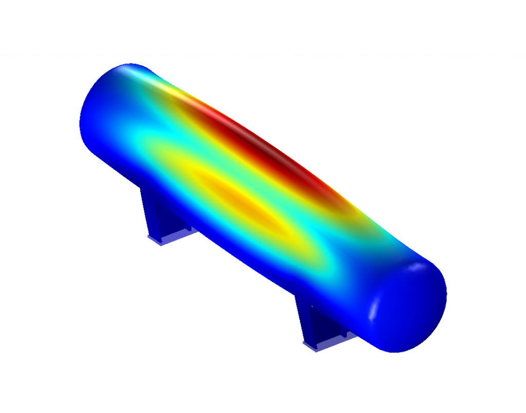
Slim bodies tend to dent or buckle when subjected to compressive forces. Cylindrical shells in apparatus engineering, for example, usually have thin walls compared to their diameter. When subjected to external pressure or axial compressive force, they can buckle and thus deform unacceptably. This type of failure is clearly separate from the fracture problem, as in most cases there is no damage in the sense of cracking or fracture when buckling occurs. The static strength limit has never been exceeded, yet the body is buckling. It is a way in which bodies „get out of the way“ of the load.
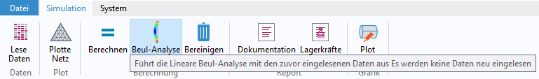
In order to check the susceptibility of your component to buckling, a linear buckling analysis can be carried out in all models.
The main result of this analysis is a load multiplier, a factor that indicates at which multiple of the applied load the body starts to buckle. This factor can also become negative, indicating to you that the load should act in the opposite direction. Which is often the case when you load a cylindrical shell with internal overpressure, as buckling can only happen with external pressure loading. As a graphical representation, you can see in the application the first buckling mode (1st mode) of the eigenmode of the bodies. This is usually the critical eigenmode, as it is the easiest to excite.
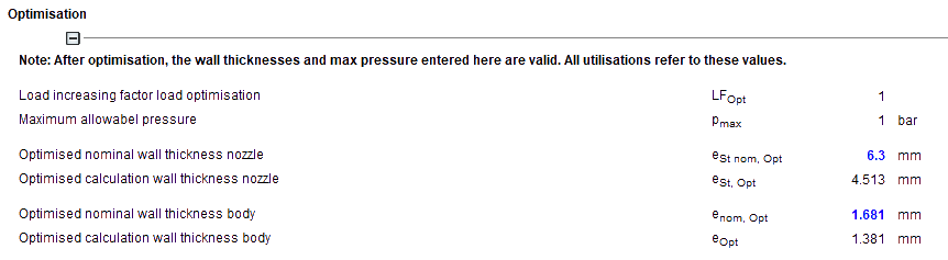
Optimisation
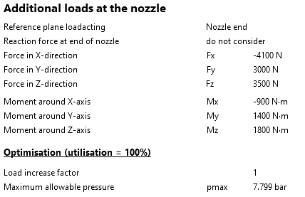
In addition to checking a specific load situation, it is often important to know what maximum load or pressure the component under investigation can bear.
Or thought of in the other direction, how slim can the component become until it just fulfils the strength conditions.
If these values are known, a component can be optimally utilised and possibly costs can be saved. Or it can be ensured that a new operating point is already covered by an earlier calculation.
Our new tool can do just that for you. The curved bottom with spigot, cylindrical bottom with spigot and flat bottom with spigot models all support the optimisation functions. Here you can choose to use the specified loads (forces and moments) to increase or decrease these loads on a percentage basis until a utilisation of 100% has been reached. Or you can determine the maximum permissible pressure for the component.
You also have the option of reducing or increasing the wall thickness of the base body or connection piece based on the specified loads, which then remain fixed, until a utilisation of 100% is reached.
Documentation
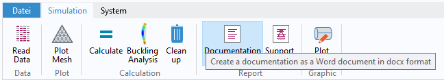
After a valid calculation, the results should be recorded in order to create a verifiable documentation. With our software you have the possibility to print our module view as usual. This contains all entries and result tables.
In addition to this printout, you can have an FE documentation created in the application with our new tool. This documentation contains all information about the simulation setup such as boundary conditions or geometric designs. In addition, the FE documentation contains all result images. Thus, you can decide yourself what to include in your final documentation and what not. With our new tool, you have everything in your own hands.
One Tool – Many Applications
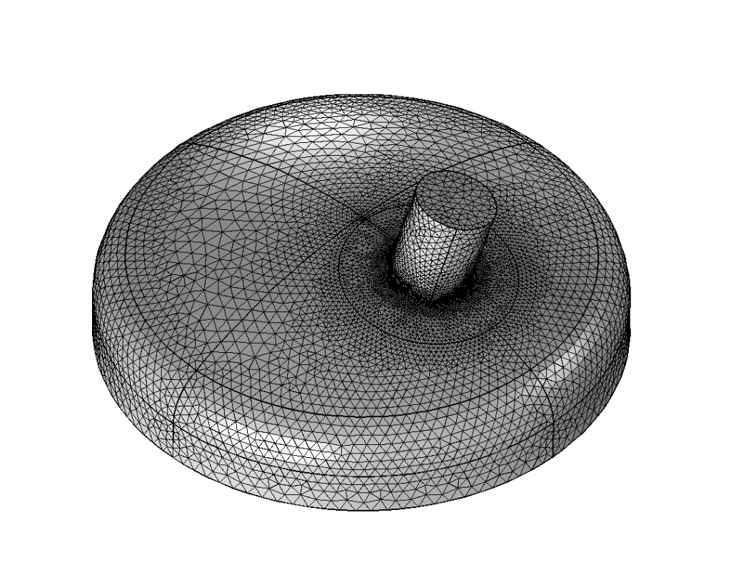
Dished heads with individual nozzles
Dished heads with openings are standard components in mechanical engineering. However, most regulations are only limited to certain arrangements and loads. In order to nevertheless obtain a verification for special requirements, it is then necessary to resort to an FE-based verification procedure.
We offer:
- Klöpperböden-type torispherical head
- Korbbogenboden-type torispherical head
- Hemispherical head
For all variants, nozzles can be designed with and without reinforcing plates.
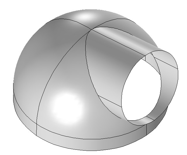
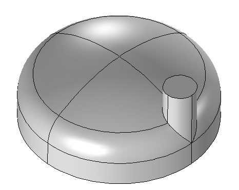
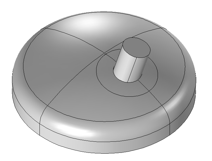
Attached, inserted and protruding nozzle designs with and without reinforcement plate can be modelled. Slanted/straight and offset nozzles, tangential nozzles or nozzles in the brim area – all in one tool.
All variants offer the possibility of applying local nozzle loads and internal or external overpressure. In addition to the pure solution run for the previously defined geometric and loading parameters, optimisations can be carried out.
Optionally, the factor for increasing the nozzle loads or the maximum pressure that can be applied can be determined, resulting in a utilisation of 100%.
Furthermore, the nozzle wall thickness or the wall thickness of the base body can be optimised so that a utilisation of 100% results.
In this way you can optimally determine the load limits of your component.
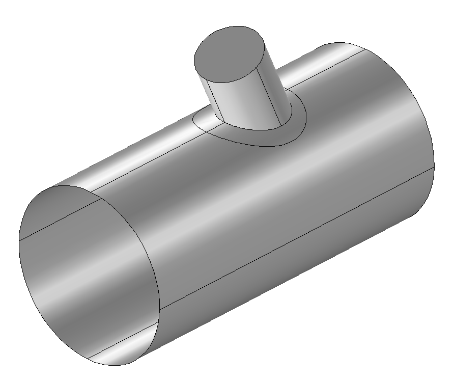
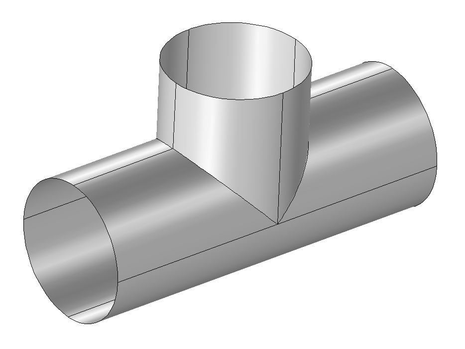
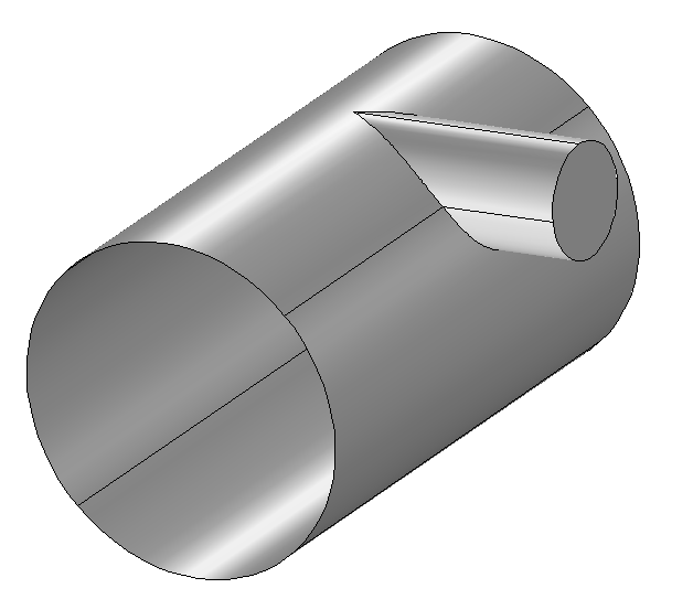
Cylindrical shells with individual nozzles
Cylindrical shells are essential in process engineering. In many cases, feed lines are required for process-related reasons, so that shells have openings with nozzles. Here, too, analytical calculations are clearly limited in their variability with regard to external loads and geometric arrangement.
With our FE Toolbox, you have the possibility to model any arrangement and loads.
It is possible to model attached, inserted and protruding nozzle designs with and without reinforcing plate. Slanted/straight nozzles, tangential nozzles or reinforced nozzles – all in one tool.
All variants offer the possibility of applying local nozzle loads and internal or external overpressure.
In addition to the pure solution run for the previously defined geometric and loading parameters, optimisations can be carried out.
Optionally, the factor for increasing the nozzle loads or the maximum achievable pressure can be determined, resulting in a utilisation of 100%.
Furthermore, the nozzle wall thickness or the wall thickness of the base body can be optimised, so that again a utilisation of 100% results. This allows you to optimally determine the load limits of your component.
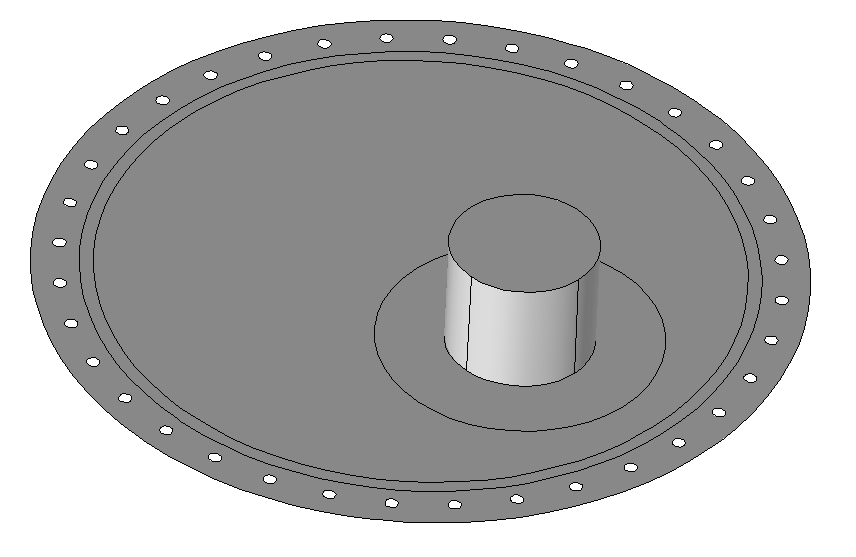
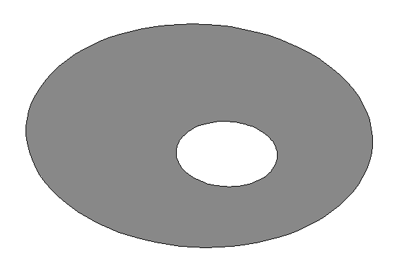
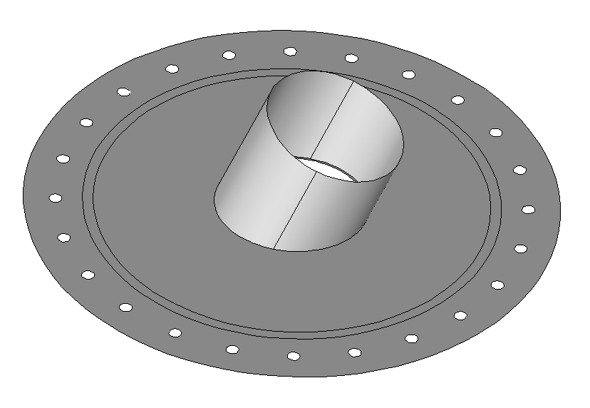
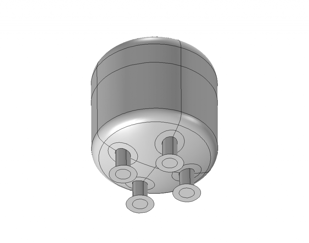
Flat ends with individual nozzles
End pieces of cylindrical shells can often be designed as flat ends. These can be, for example, blind flanges with an opening or end heads of a heat exchanger with a withdrawable tube bundle.
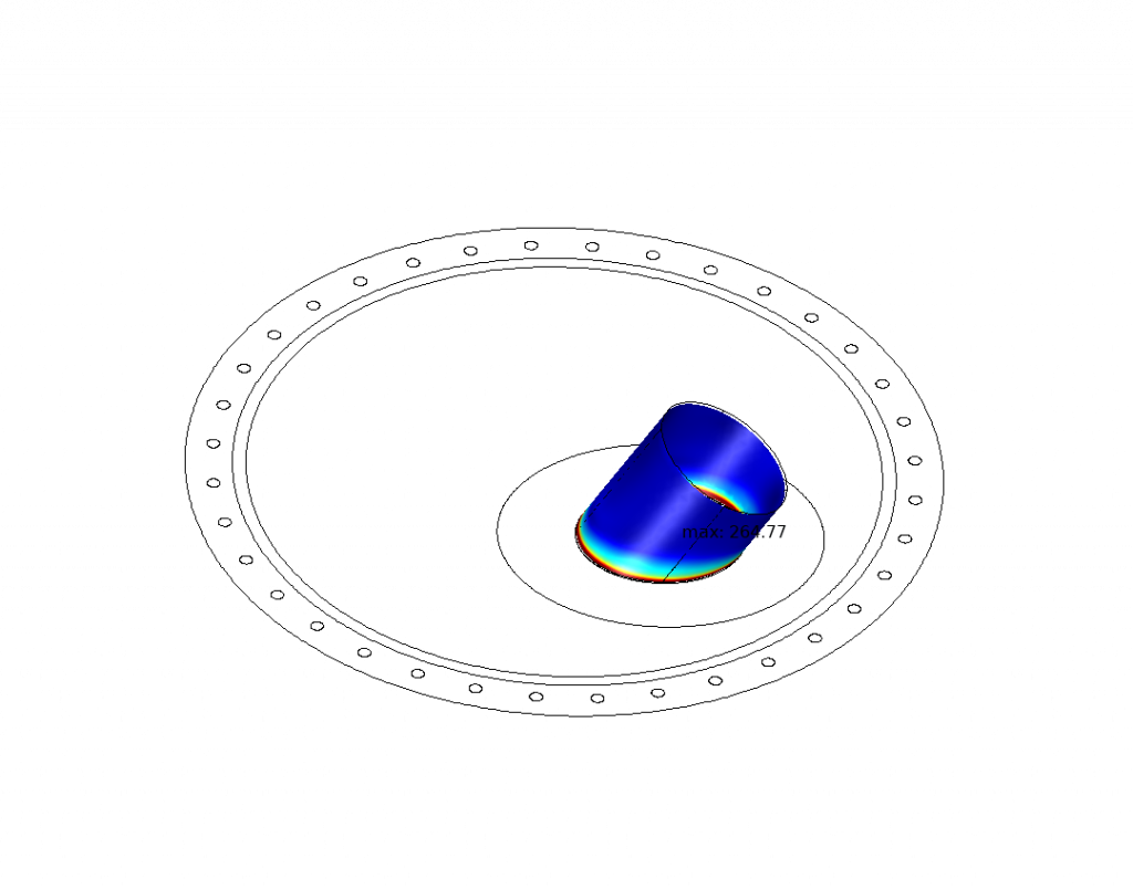
Here, too, the requirements are very different and often verifications with loads in and around all three spatial directions have to be applied and checked.
Our FE Toolbox offers the possibility to test flat floors with single nozzles for any loads.
Bolted flat floors (with additional edge moment) or welded flat plates with and without nozzles can be calculated.
Sloping/straight nozzles, pure opening or reinforced nozzles.
All in one tool.
Flat ends also offer the possibility of applying local nozzle loads and internal or external overpressure for all variants.
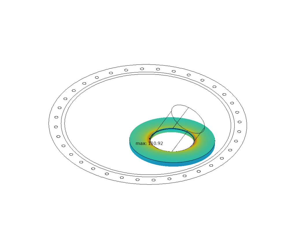
In addition to the pure solution run for the previously defined geometric and loading parameters, optimisations can be carried out.
Optionally, the factor for increasing the nozzle loads or the maximum pressure that can be applied can be determined, resulting in a utilisation of 100%.
Furthermore, the nozzle wall thickness or the wall thickness of the base body can be optimised so that a utilisation of 100% results. In this way you can optimally determine the load limits of your component.
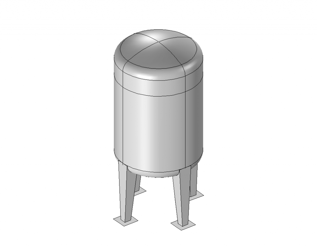
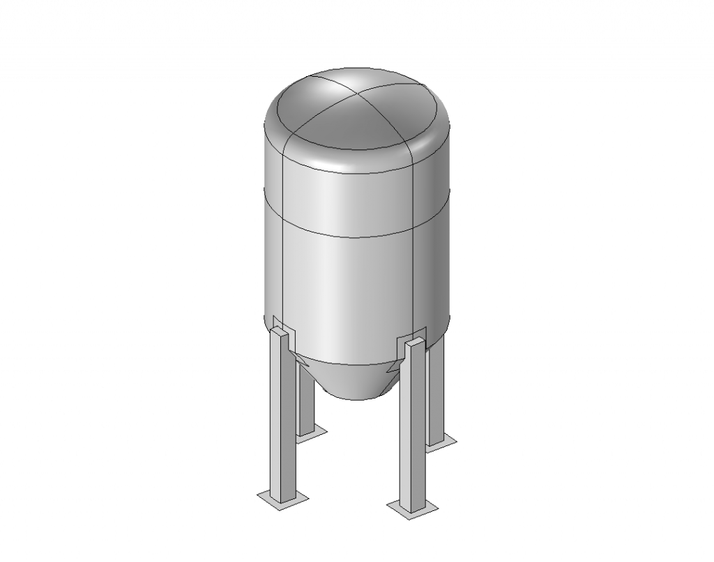
Vessels on leg supports
Supporting structures in vessel construction are available in a wide variety of designs. One type of construction can be to design standing tanks on feet.
Our FE Toolbox offers you a variety of geometric options for the arrangement and design of the pedestals, for example as upright containers on round, square or conically profiled pedestals. Feet can be designed with or without reinforcing plates on the container. The feet can be attached to the side or directly to the lower floor. In addition, any number of feet, but at least three, can be fitted.
In addition, you have the choice of designing the containers with curved or conical bottoms. This allows you to create a very large number of designs.
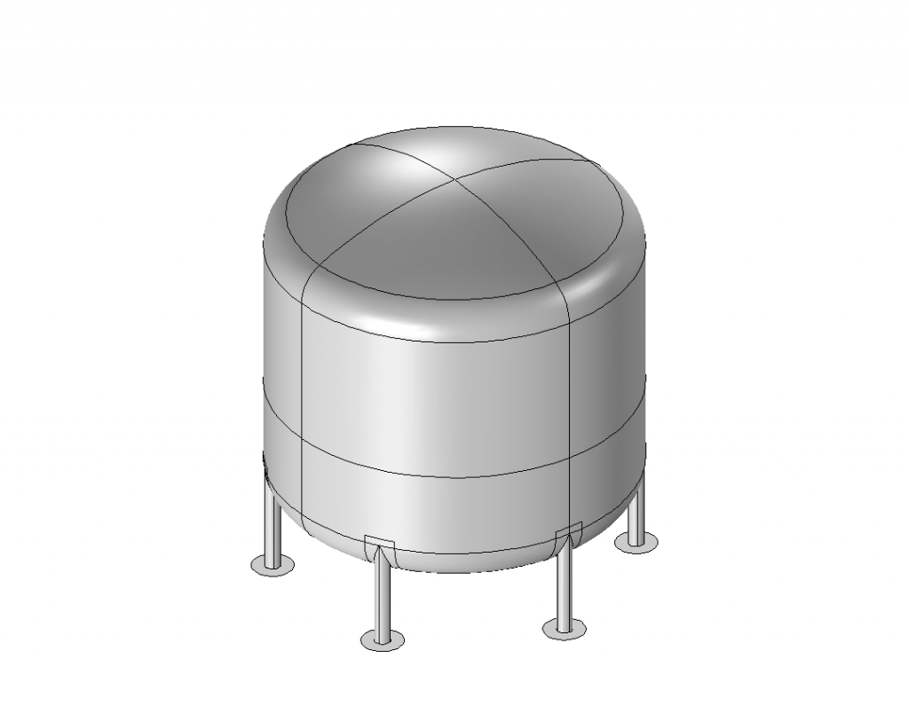
Just as the geometry offers many possibilities to design the container, the loads can also be very different. As mentioned before, our new tool offers the possibility to consider a variety of external loads. For example, containers on feet can be subjected to additional loads such as hydrostatic filling, earthquake loads, wind loads, roof loads such as snow loads or platforms in addition to the internal pressure load. In addition to these loads, forces and moments can in turn be applied in and around all three spatial directions. Thus, the supporting structure can be verified for a very large number of load cases.
Our tool also offers the possibility to carry out a buckling analysis to check the stability against shell buckling or buckling.
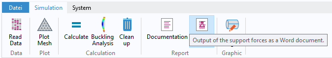
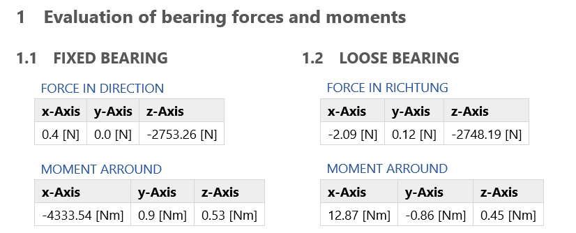
Furthermore, you get the bearing reactions for each foot individually. These are entered in tabular form in a separate document.
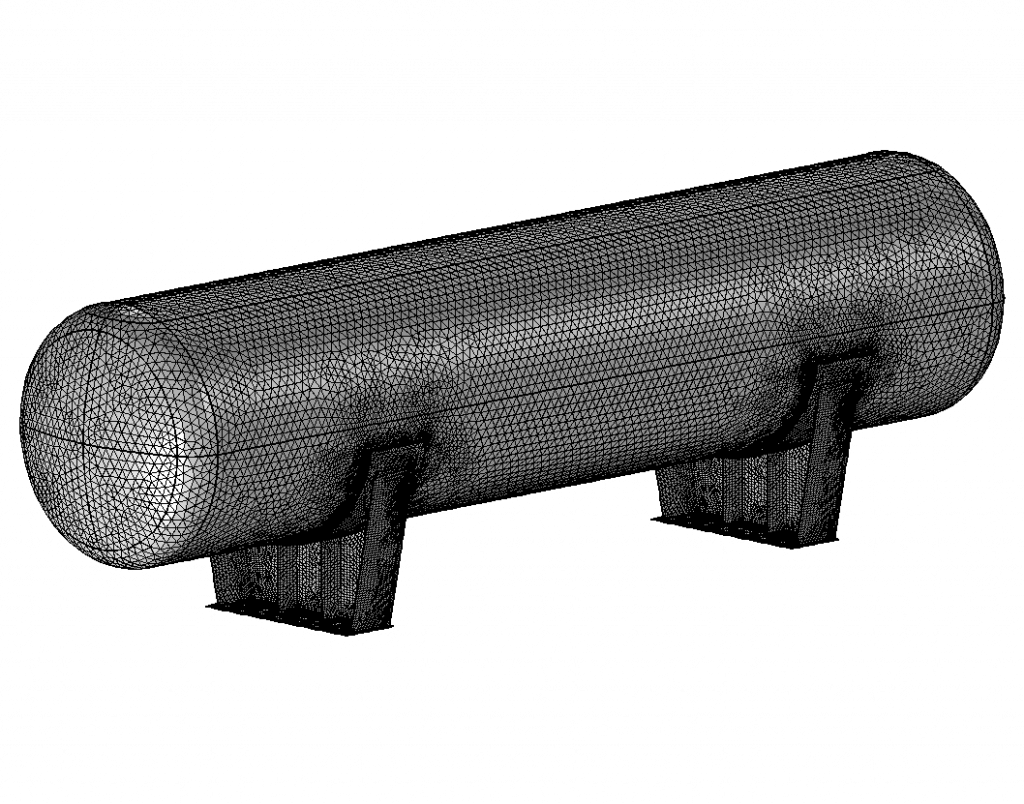
Vessels on saddle supports
For containers on support saddles, the standard sets of rules only offer a limited possibility of load mapping. These are mostly limited to internal pressure and dead and additional weight. However, different load verifications of the earthquake load or loads from the transport of the containers are often required. Here, too, there is usually only the way to the FE calculation. With our new tool, we offer you the possibility of representing a large number of geometric designs of saddles and complex load situations.
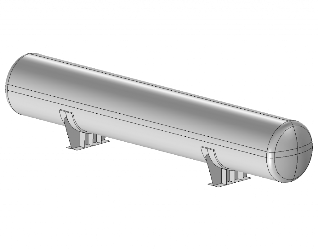
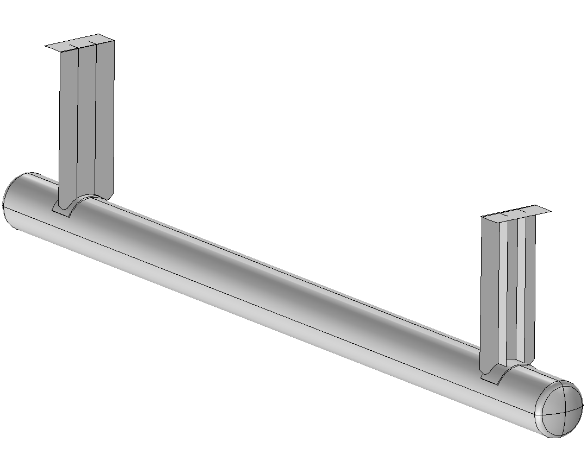
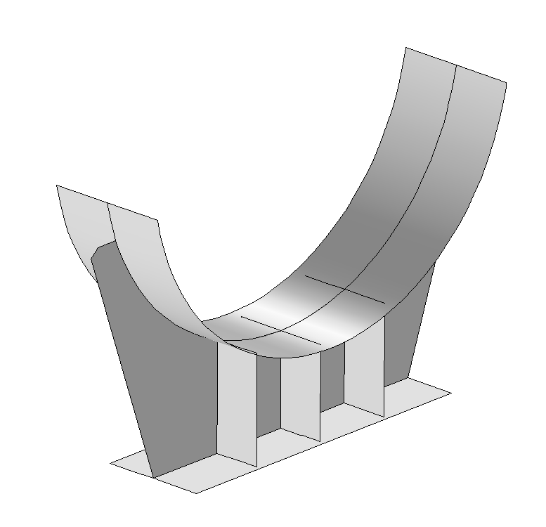
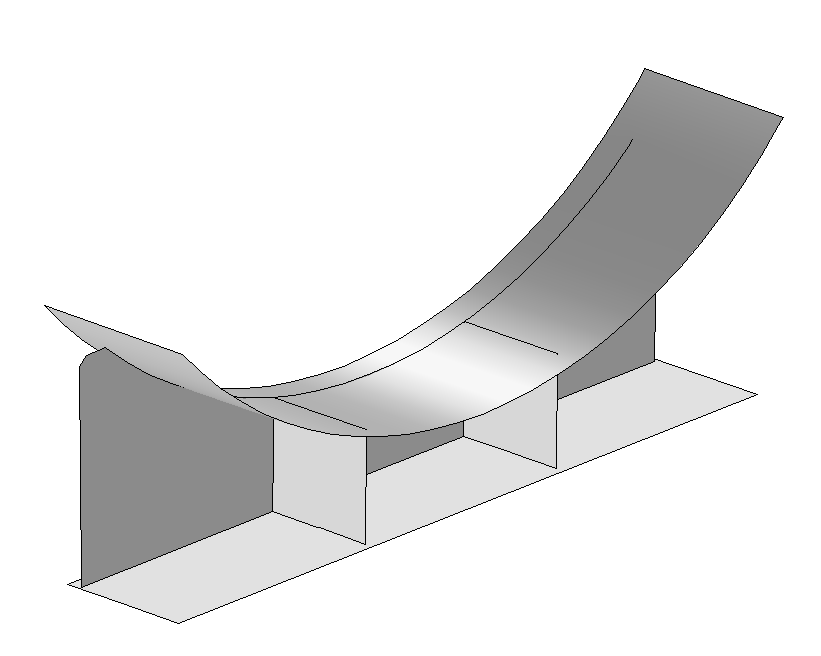
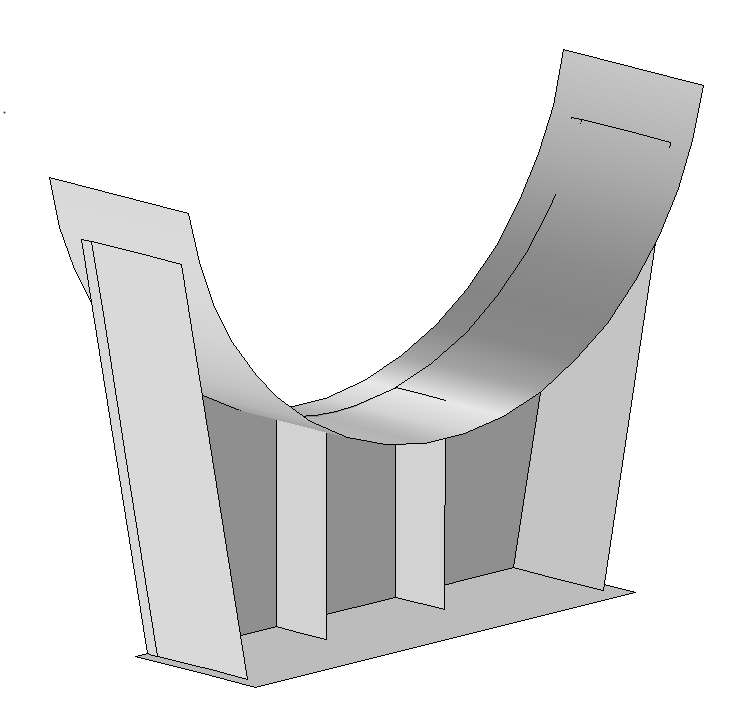
There are (almost) no limits to the design possibilities – side plates, number of ribs, position of web plate and wrap angle as well as alignment of the saddles to each other and all general dimensions can be chosen at will.
Like the containers on pedestals, horizontal containers on saddles can be subjected to additional loads such as hydrostatic filling, earthquake loads, wind loads, roof loads such as snow loads or platforms in addition to the internal pressure load. In addition to these loads, forces and moments can in turn be applied in and around all three spatial directions. Thus, the supporting structure can be verified for a very large number of load cases.
Our tool also offers the possibility to carry out a buckling analysis to check the stability against shell buckling or bending. Furthermore, you get the bearing reactions for the two saddles individually ( loose and fixed bearing). These are entered in tabular form in a separate document.
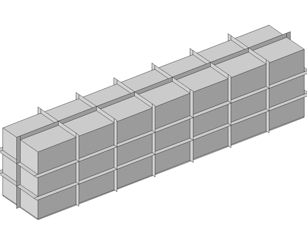
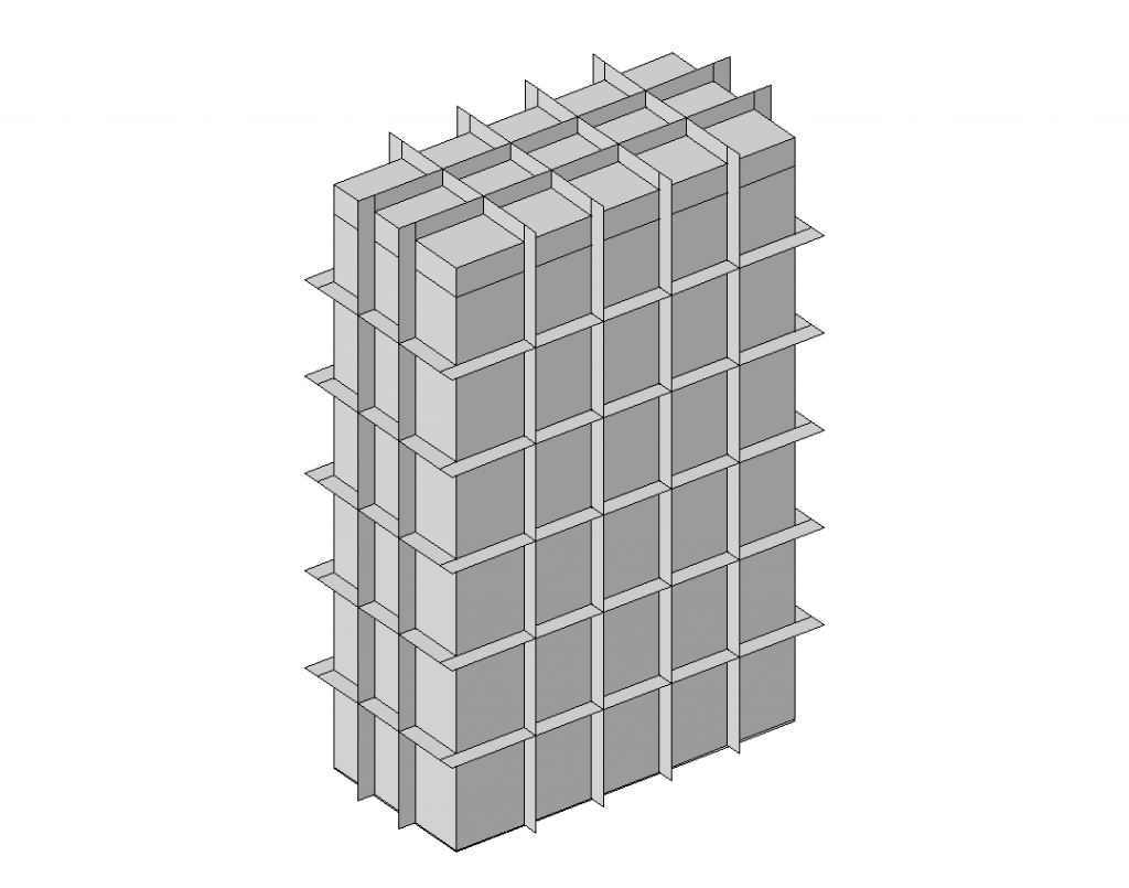
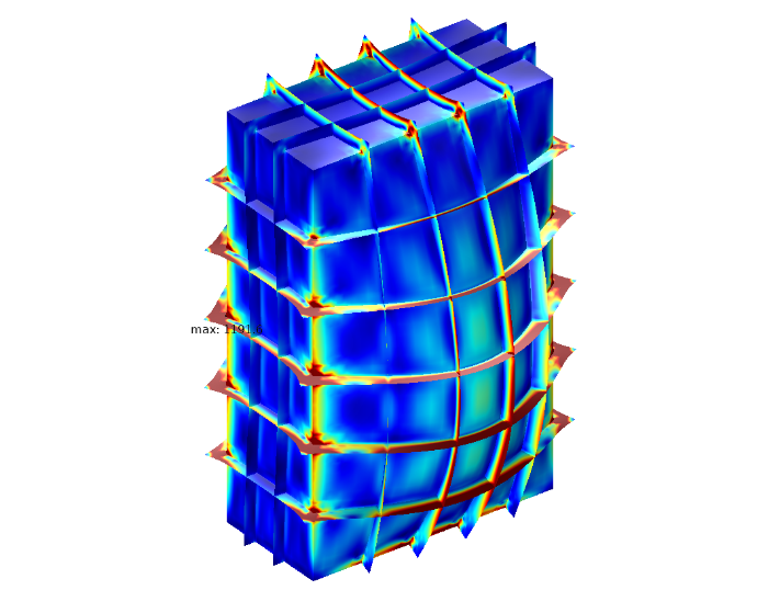
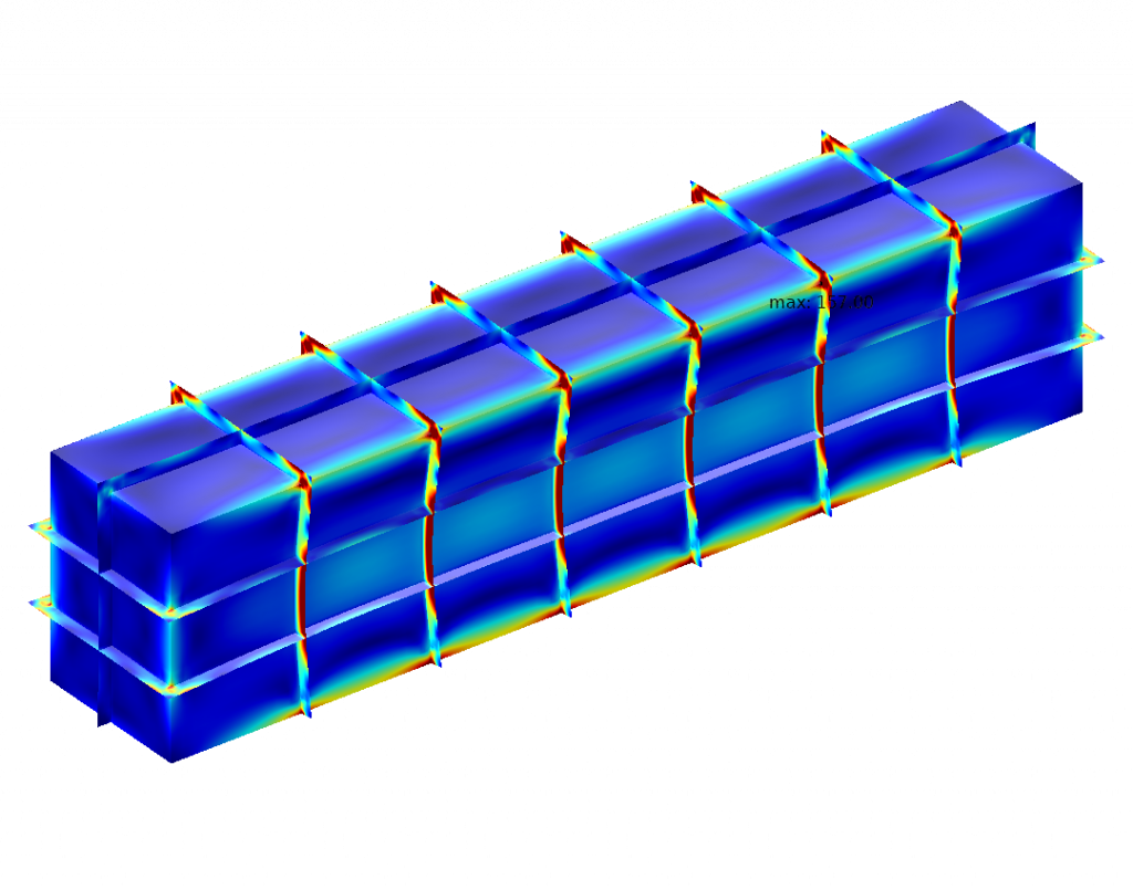
Reinforced Rectangular Vessels
When you think of rectangular vessels, you usually don’t think of pressure vessels. Nevertheless, it is becoming more and more common for rectangular vessels to be designed as pressure vessels for structural or process-related reasons.
Bodies that are under internal pressure want to become a sphere. This is the physically most favourable shape. A shell would then only be loaded in the cross-section in the normal direction. In rectangular containers, high bending stresses occur at the sides and corners. To absorb these, reinforcing ribs are often added. This changes the load situation significantly.
With our new tool you have the possibility to check reinforced rectangular containers for strength and shell stability (shell buckling). Any number of ribs can be attached. Like the containers described above, the component can be loaded with forces and moments in and around all three spatial directions. Furthermore, wind loads, roof loads, earthquake loads, additional loads and a hydrostatic filling can be applied.